
In Part I, we gave you a very basic overview of Web Dynpro. In this part we will create one Web Dynpro Application.
Before we develop our first Web Dynpro application, let me ask, what steps do you follow while writing a normal ABAP program/report in SE38/SE80, which has a selection screen; an output screen and a custom transaction code?
Let me note down that steps:
ABAP Editor or Object navigator
- Go to SE38 or SE80 and create a program. Give the description and attributes and save it in transport or as local object.
AT SELECTION SCREEN and SCREEN EVENTS - Declare the selection screen parameters and select options thereby creating a selection screen.
- Declare global data which would be used throughout the program.
START OF SELECTION - Fetch data from database tables.
- Try to modularize (using subroutines) your data fetches if from numerous tables.
- Declare local data which would be used in subroutines.
END OF SELECTION - Massage the data and prepare the final data for output (modularize here as well).
- Display the output.
- Activate your program.
Create Custom T-Code for the program using SE93. - Create transaction for your report.
Congratulations!!! You just created your first Web Dynpro Application. No kidding. We will create a cool WD report in similar steps as mentioned above.
Let’s assume the requirement of your functional specification says: Create a Portal screen which would display the SAP user’s first name and last name. Use table view USER_ADDR to retrieve data.
Happy to get your first Web Dynpro Functional Specification. Let’s jump into the system.
Please scroll up and walk through the steps.
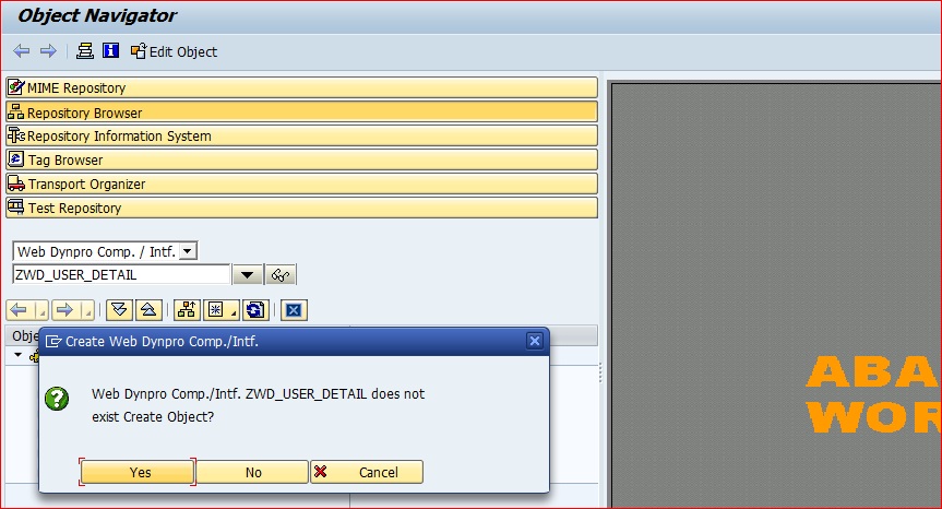
Step 1: Go to SE80 Object Navigator. Select Web Dynpro Comp./Intf from the dropdown. Give a name to the WD component which you want to create and hit enter. You will get a message as shown in picture below.
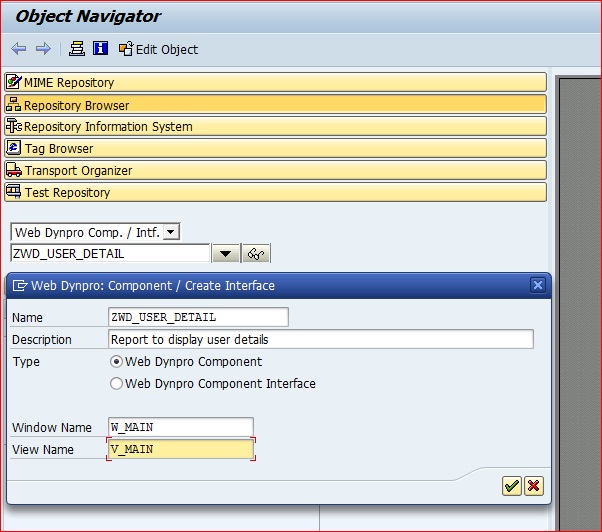
Give a meaning description and name (as shown in next picture) for your default/main Window and View. Name it as per your project standard. Usually we have WI_ or W_ for windows and VI_ or V_ for views. Then save it. Give appropriate package and transport number else save it as local object if you do not want to move to next environment. Now you have created your first WD component which is empty.
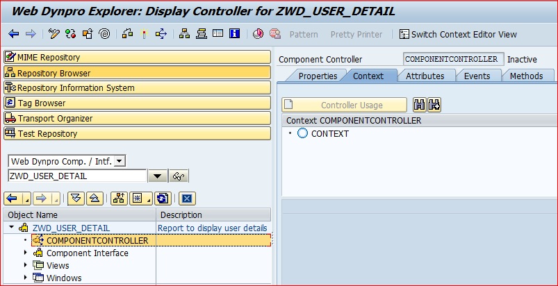
Step 2: Declare selection screen parameters. Since it would be used globally, let us define the variable (context) in the component controller (global/top). Double click on COMPONENTCONTROLLER in the left panel and click the Context Tab in the right panel.
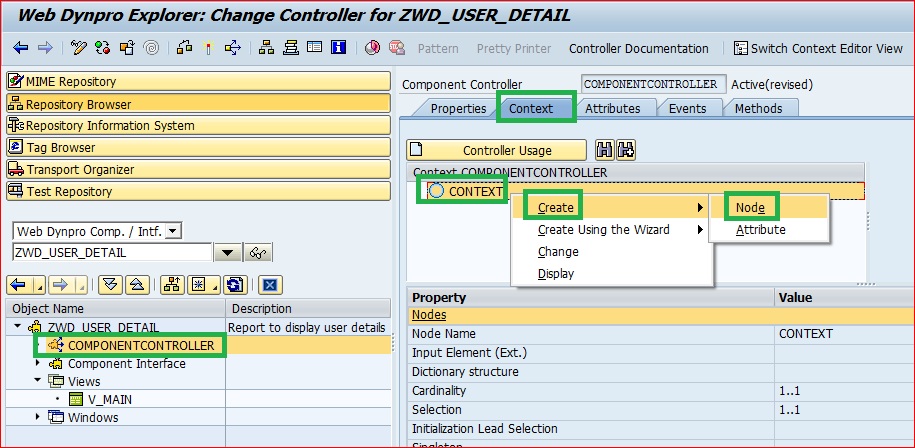
Right click the CONTEXT ->Create-> Node. This is the name of your structure used in selection screen parameter. We generally use CN_ for context node and CA_ for context attribute. Give a meaningful name and hit enter.
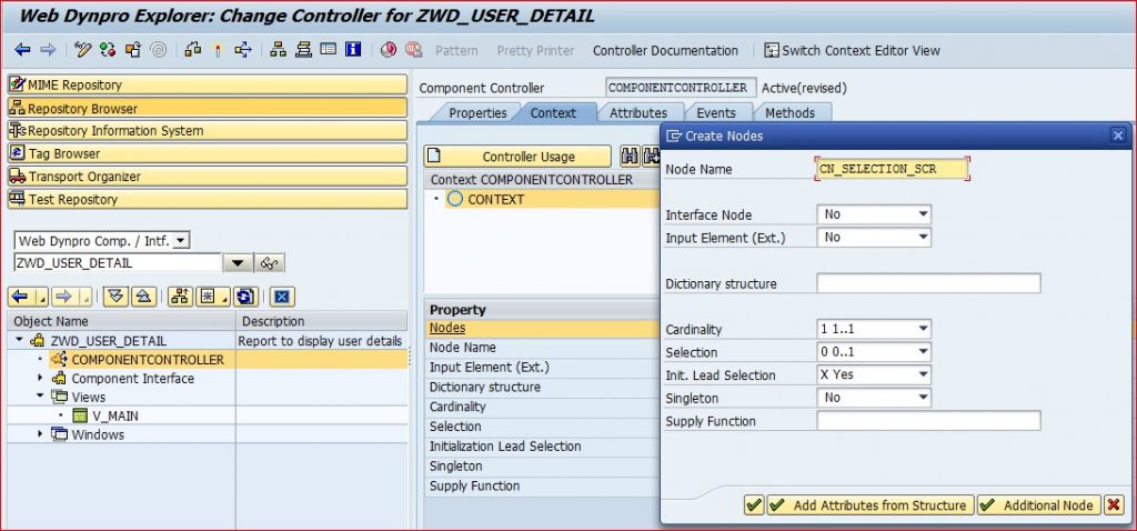
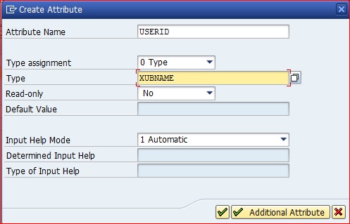
You created a structure, but it is empty. You need fields in the structure to make it complete. Right click on the context name CN_SELECTION_SCR ->Create->Attribute; give a name and data-type of the field and save and activate all the objects of the components. This is the global variable for the selection screen.
Tip: Try to activate your component after every major change/development so that if any error, you can find and resolve it easily. If you activate at the end, after creating everything, then it might be little more tiresome to resolve the issue.
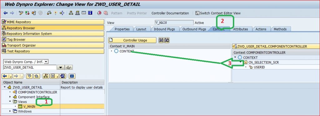
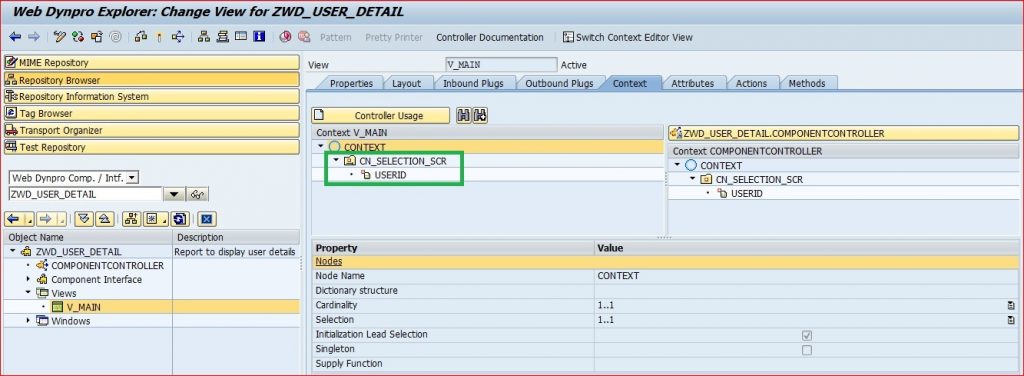
As I mentioned in PART I, the global variable are not directly available to the views. We need to make the view know that the global variable (CN_SELECTION_SCR) would be used in that view. This can be done by dragging the COMPONENT CONTROLLER Context attribute to View Context. Expand the View in the left panel. Double click on the view name. Click the Context Tab on the right Panel. On the right panel there is a split. Left for View and Right side for COMPONENT CONTROLLER Context. Left click on the CONTEXT CN_SELECTION_SCR hold and drag and put it on top of V_MAIN CONTEXT on the left. This is like USING/CHANGE Parameters of SUB ROUTINE (PERFORMS) in normal program.
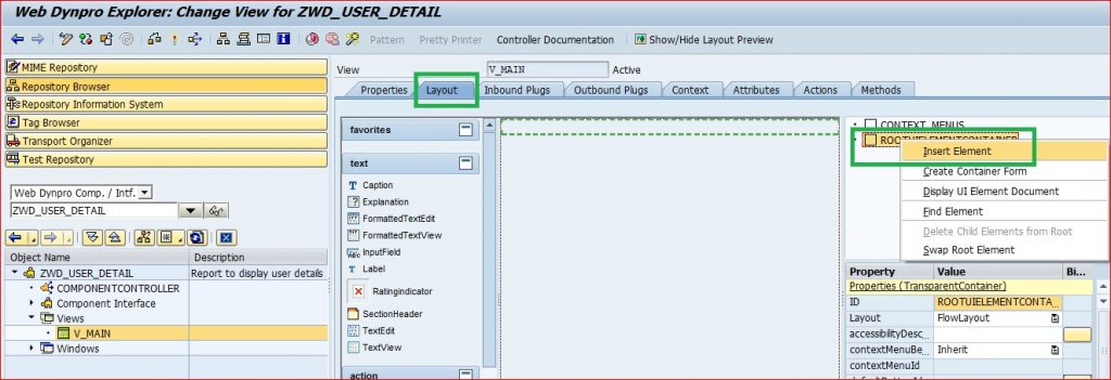
Now we are good to design the screen. View->Layout. Right click on ROOTUIELEMENTCONTAINER and insert one TRANSPARENT CONTAINER. Transparent containers are just holder of UI elements. Usually, related UI elements are collected in a TRANSPARENT CONTAINER.
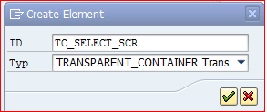
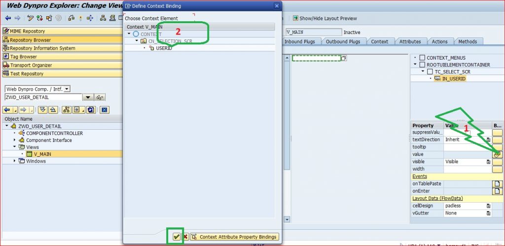
Now let us define an input parameter for the screen (just like we do in SE38). Right click on Transparent Container and create Input field.
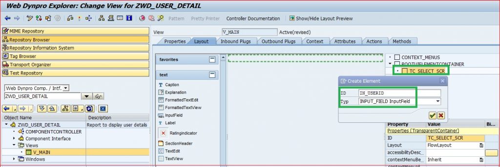
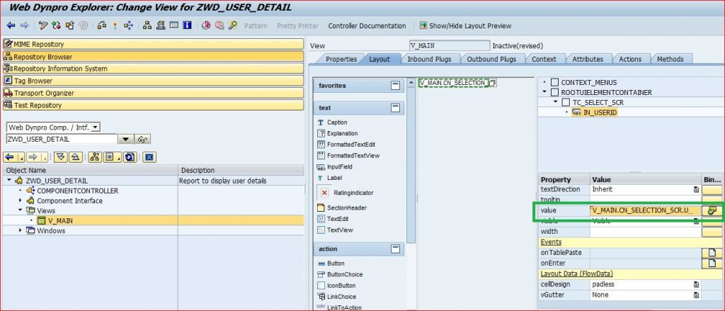
This is just a variable, but what data would it hold? We will link this input field to the USERID field defined in the context CN_SELECTION_SCR. Click on the yellow icon on the right side of value property and bind it with USERID. It is just like our PARAMETERS: P_INPUT TYPE XUBNAME. Any value entered in this parameter in selection screen is passed to P_INPUT and it can be used in the whole program.
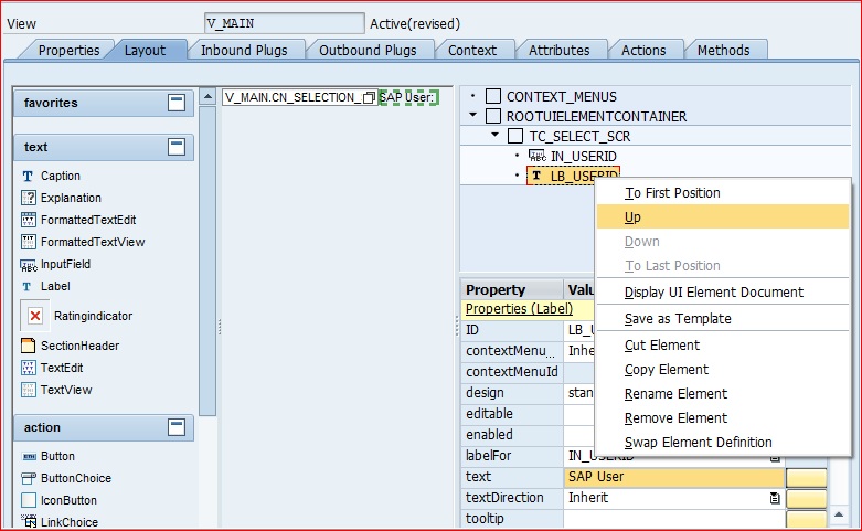
Let us give a meaningful label to the selection screen parameter. Just like in SE38, we create Selection Screen text, in the similar way, a LABEL UI element tagged to Input Field would act as its text, which would be displayed in the selection screen. Right click on Transparent Container and create the Label. Populate the Label For field.
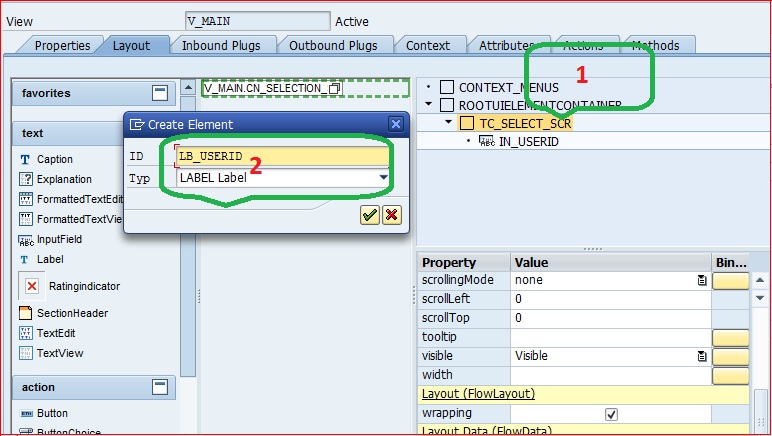
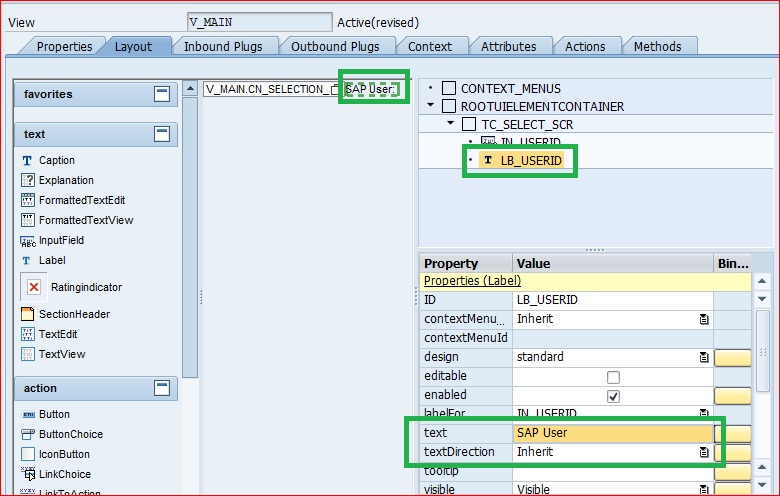
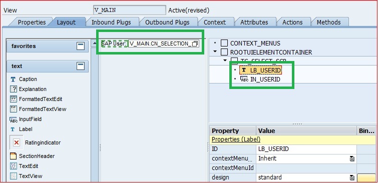
By default it would be on the right side of the field. Move it up so that it is on the left side.
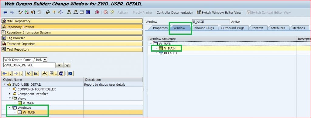
Let us look how the window looks. In the main window, the default main view is assigned. So, whatever we have designed till now is available to be displayed in the window.
Step 3: WD Application like our familier Transaction Code created in SE93:
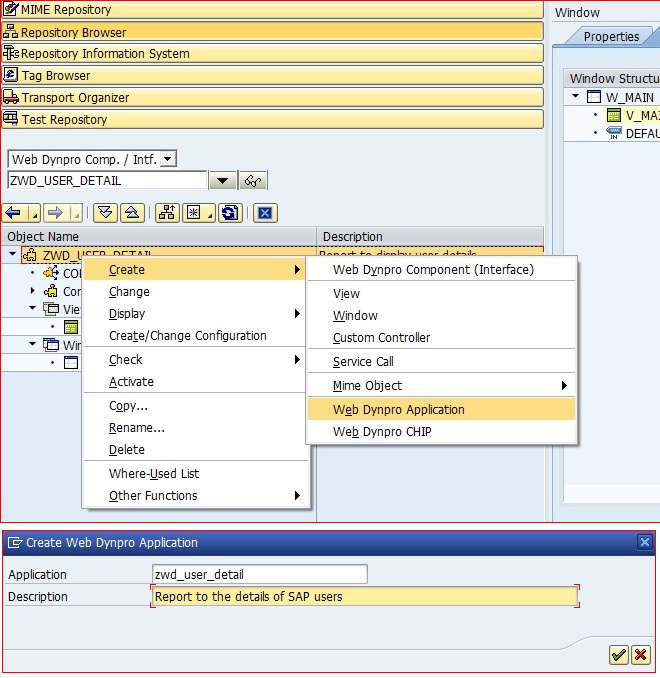
At this juncture, you would be tempted to see how your selection screen looks like. For that we need to create the application (like you need a transaction code for a program). Right click on your Component and create the application and save it.
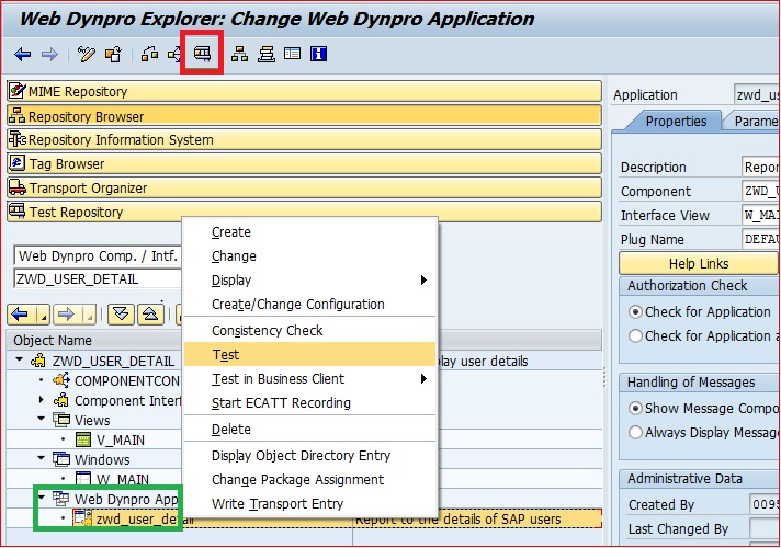
Now you can execute it by F8 or by right clicking the application and Test.
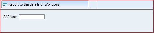
Congrats!! Your screen look perfect..
Step 4: Interactive Buttons:
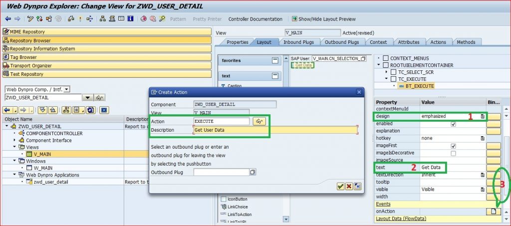
Screen is ready, but user would need something to interact. So, button is needed. Let us create a button, which would let the system know that some action is done and it has to perform some function.
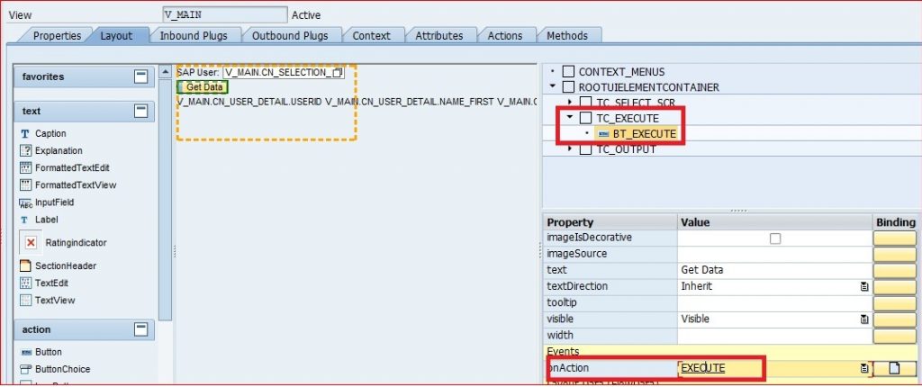
Create another Transparent Container. Right click on transparent container and create a Button UI element.
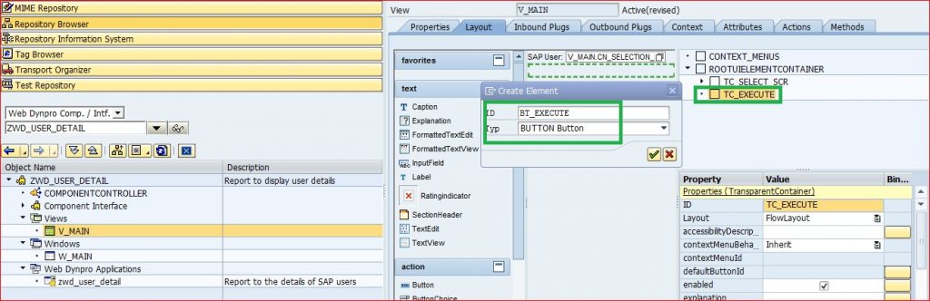
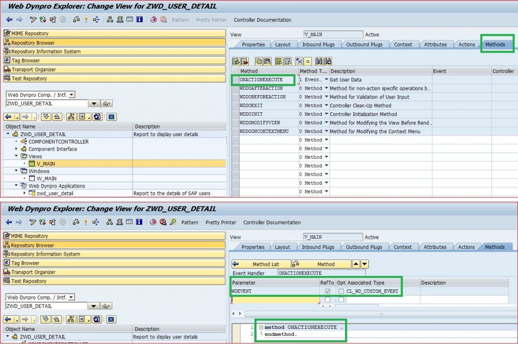
Link an action to the button. Click on the create icon on the right of onAction Events property. Give a meaningful name and description to the action. A method is created for this action in the background as shown.
Step 5: Preparation to display the output:
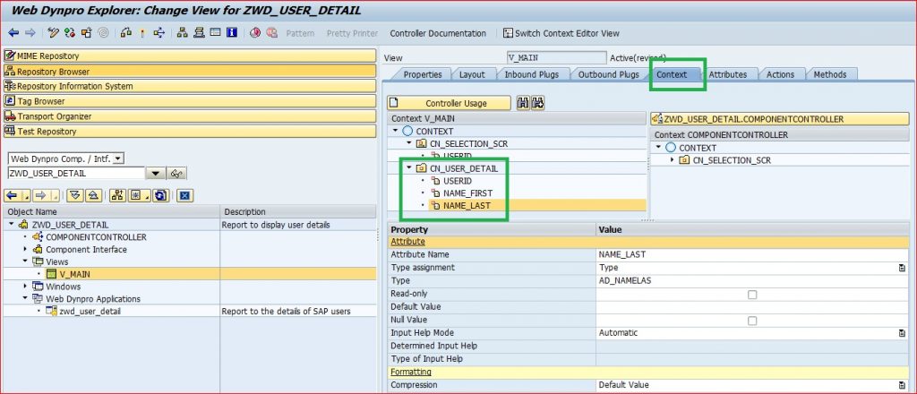
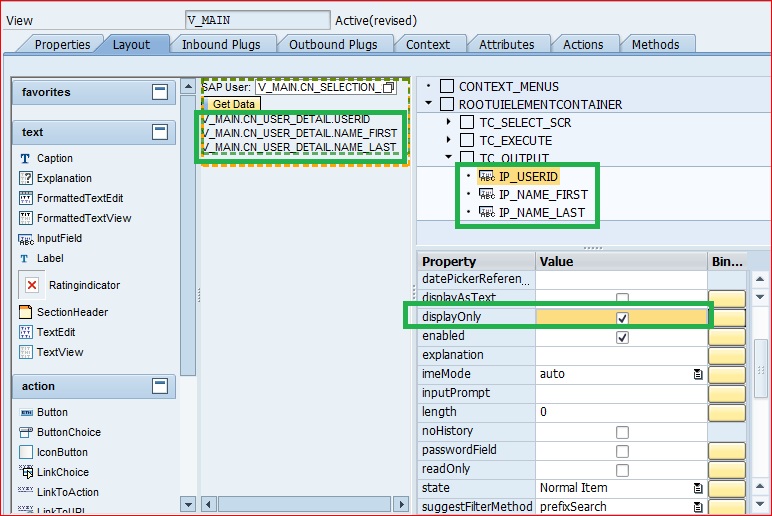
Now, we have the input field and button. But, still we do not have the place holder for final output. So, let us create another CONTEXT (CN_USER_DETAIL) which would be local to the view (assuming this context would not be used in any other place). In the context define three attributes, USERID, NAME_FIRST and NAME_LAST (referring to table view USER_ADDR).
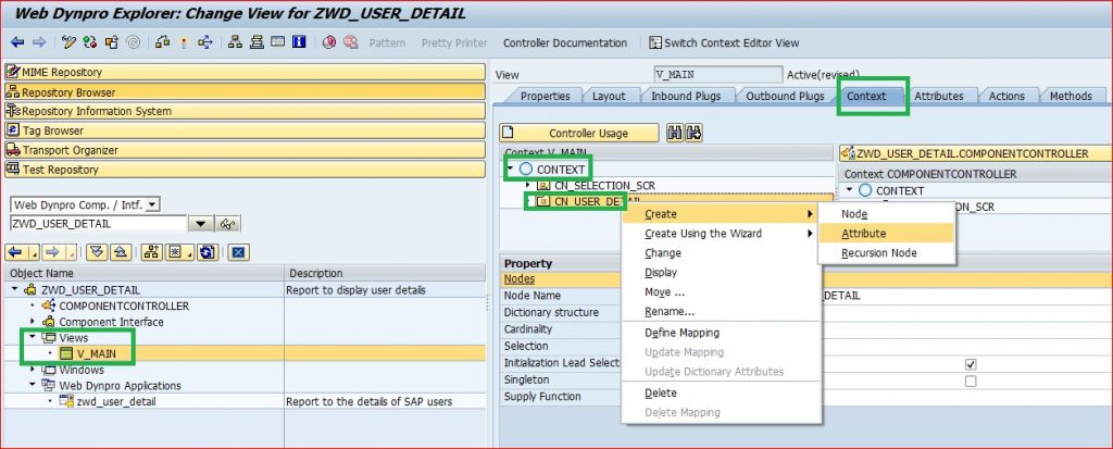
So output type is defined but it is not yet linked to any variable. Let us create three input fields in a transparent container and link the values to corresponding fields in the CONTEXT CN_USER_DETAIL. Below it is shown for only USERID. We need to do for all three.
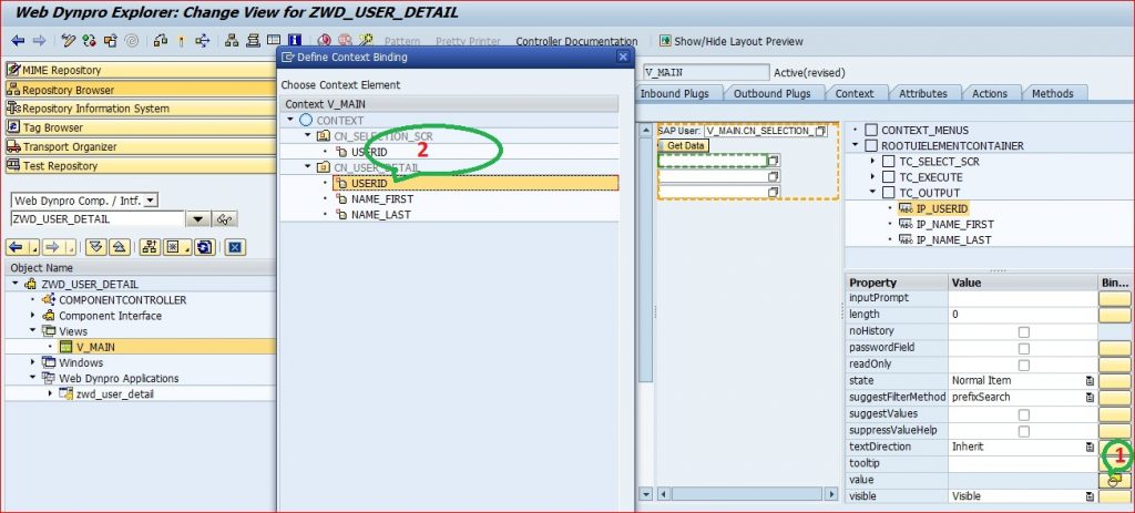
Since these three attributes would be used for display only, let us check the displayOnly property for all three.
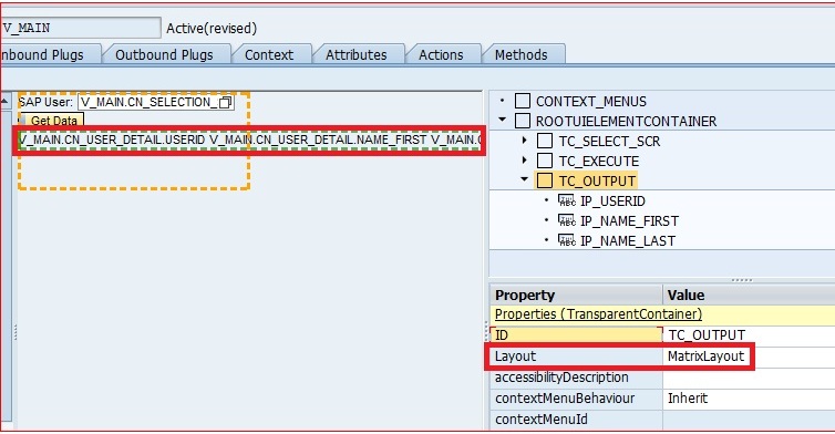
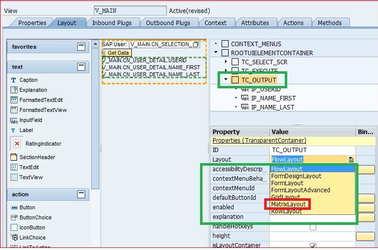
You would like to see the three attribute in one row, not in one column. For this we need to change the layout type to Matrix Layout. We would speak more about Flow, Matrix data and Matrix Head data layout in subsequent sessions.
Let us see the screen again.

It has the input field and the execute button. But, what will the button do, we have still not defined the data extraction and display logic.
Step 6: Start of Selection:
Read the value entered by user in the INPUT Field USERID in the portal screen. This can be easily done by reading the CONTEXT which is linked to USERID field. User the MAGIC WAND (highlighted with number 1) provide by SAP. Most of your Web Dynpro code or at least the skeletal code snippet can be generated by using this Magic Wand (wizzard). You need to go to the Methods tab of the View or double click the Execute action of button BT_EXECUTE.
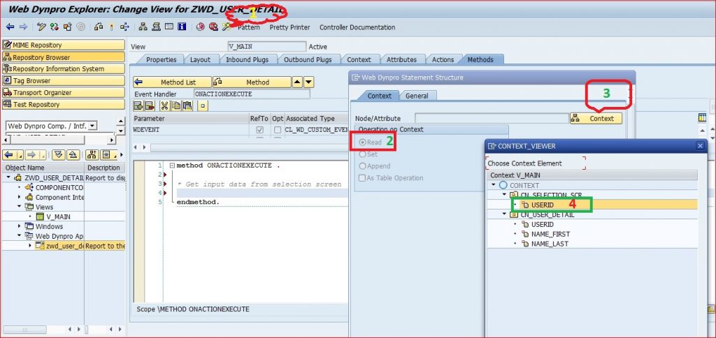
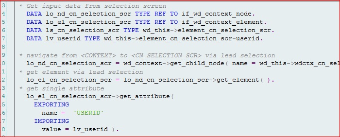
Check the READ radio button and then hit the CONTEXT and choose the CONTEXT field which is bound/linked to the INPUT field. Hit enter. All the code is generated for you. Remove the commented code and some check codes which are not needed for our scenario. Whatever user enters in IP_USERID field in selection screen is available in variable lv_userid.
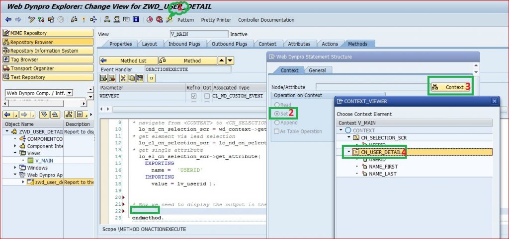
Now, whatever data you want to display in the three attribute of the output context, we need to SET them, i.e. we can use the same magic wand to SET the CN_USER_DETAIL context as shown.

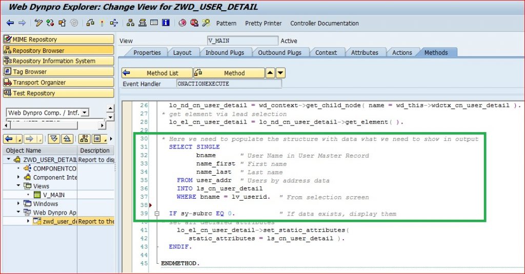
The LS_CN_USER_DETAIL structure would display the user details. But, the structure is still empty. We need to select the data and populate the structure. We will write a simple select statement and populate the structure as shown.
PS: This is the only piece of code we write for this application.. Isn’t it awesome..
Uffff !!! We have done all steps. Fetched data based on input field and populated the output structure. And linked all the UI elements to the underlying context.
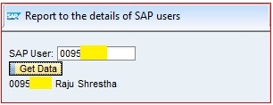
Let us test our first baby.. Let me enter an SAP user id present in our system and hit the Get Data button. Abracadabra… Details are displayed..
This was one of the simple valid project requirements. Please do not smile, this was one of the requirement in one of our project We would add on the complexity and explore the different features of Web Dynpro in subsequent parts. Till then, please play around this component and stay tuned.


