A B2B integration scenario involves many tasks associated with the exchange of business messages between the business partners. The required tasks include defining interfaces for the involved partners, creating mappings between the interfaces, generating the runtime artifacts and, finally, modeling the integration scenario. SAP Integration Advisor (IA) and SAP Cloud Integration play a key role in simplifying and streamlining the integration tasks.
This post focuses on:
- how to inject the mapping artifacts generated by IA into CI
- How to configure and run the CI integration flow to consume the mapping artifacts
Prerequisites
- Integration Suite, Standard edition or Premium edition
- Process Integration Runtime, plan api
Step 1: Reuse Prepackaged Integration Content
SAP Cloud Integration (CI) delivers rich prepackaged integration content out of the box that enables you get started quickly.
In the tenant of CI, navigate to the Discover tab, you can find the prepackaged integration content for IA.
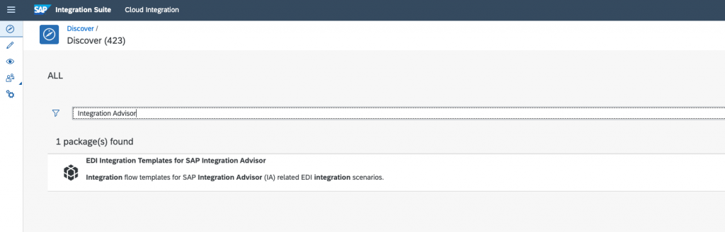
This package provides the required template of inbound and outbound integration flows for the processing of UN/EDIFACT (and UN/EDIFACT subsets-like GS1 EANCOM or Odette EDIFACT), ODETTE, ASC X12 or cXML interchange to SAP IDoc, SAP SOAP or vice versa.
Copy the prepackaged content to your workspace (Design tab) by clicking the Copy button:
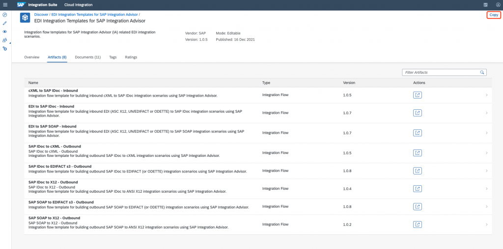
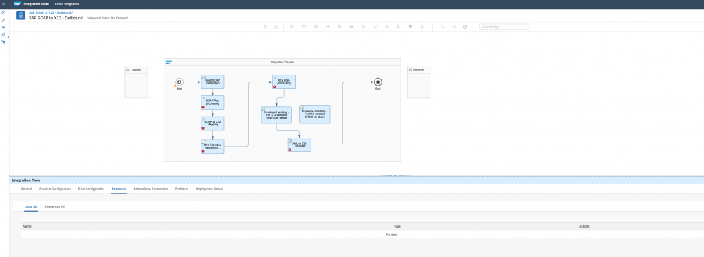
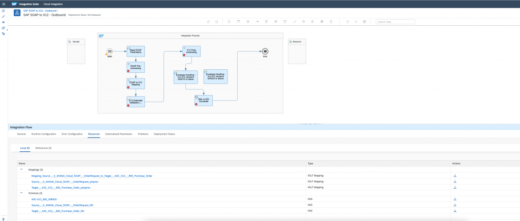
In this post, we will reuse the iflow SAP SOAP to X12 – Outbound. Navigate to the Design tab and open the artifact:
Step 2: Inject The Mapping Artifacts Generated by IA into your CI tenant.
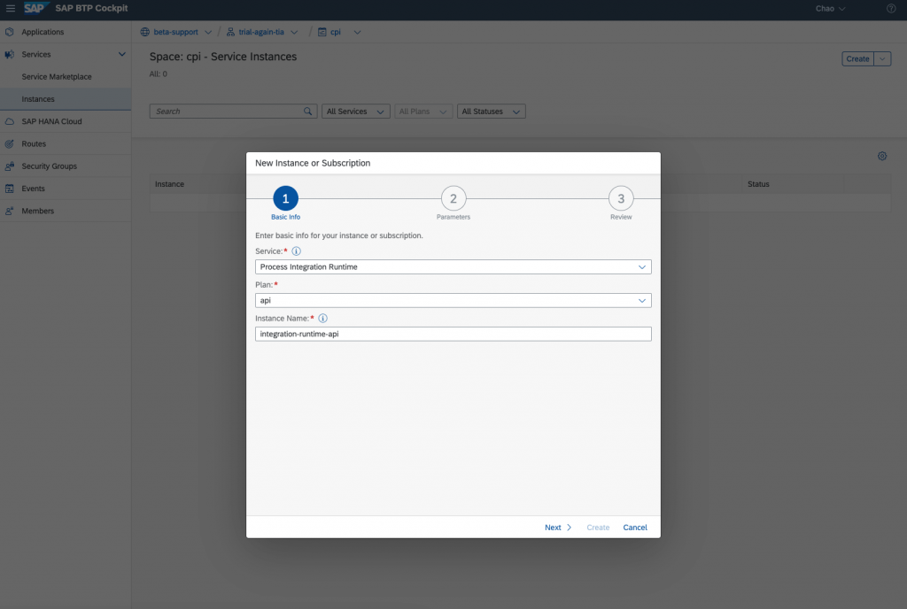
1. Create instance and service key
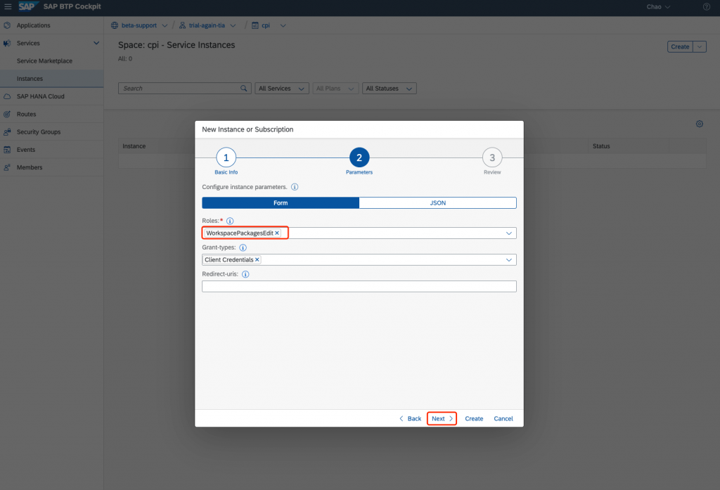
Create an instance of the service Process Integration Runtime, plan api, with role WorkspacePackageEdit:
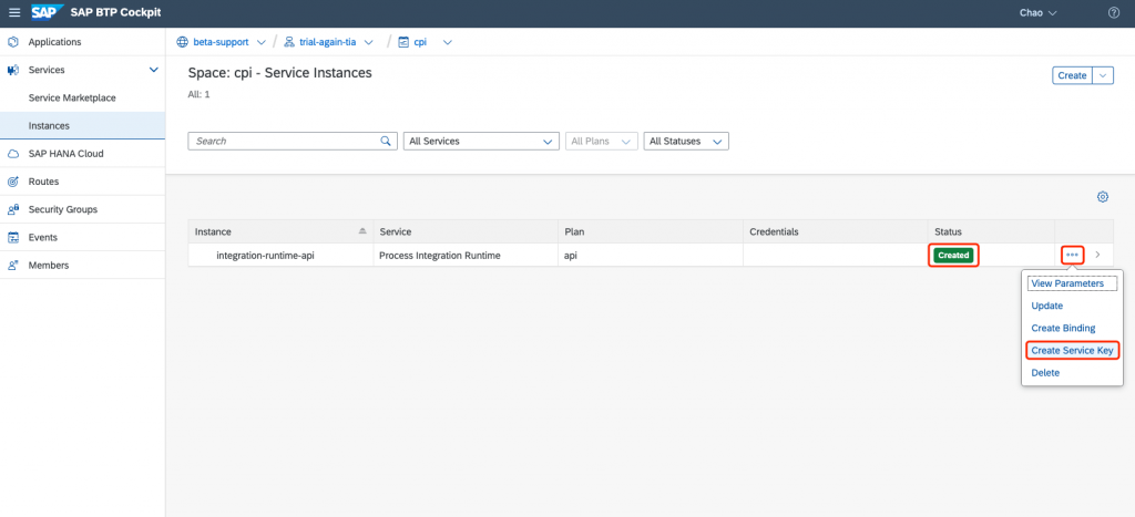
Create a service key for the instance:
2. Create CI destination
A CI destination needs to be established so that IA can find the target endpoint of the CI to inject mapping artifacts.
Login to SAP BTP cockpit and navigate to your subaccount. Choose Destinations -> New Destination. Provide detailed information:
| Field | Description |
| Name | This field is case-sensitive. <br />Note: The destination name must start with the prefix CPI_TENANT_. |
| Type | HTTP |
| Description | You can provide a description for your reference. This field is optional. |
| URL | For CF, enter the url displayed in the service key you created in the previous step. |
| Proxy Type | Internet |
| Authentication | Enter the authentication details. <br />Note: The supported authentication modes are: BasicAuthentication and OAuth2ClientCredentials.<br />In this post, we choose OAuth2ClientCredentials |
| Client ID | Enter the clientid displayed in the service key you created in the previous step. |
| Client Secret | Enter the clientsecret displayed in the service key you created in the previous step. |
| Token Service URL | Enter the tokenurl displayed in the service key you created in the previous step. |
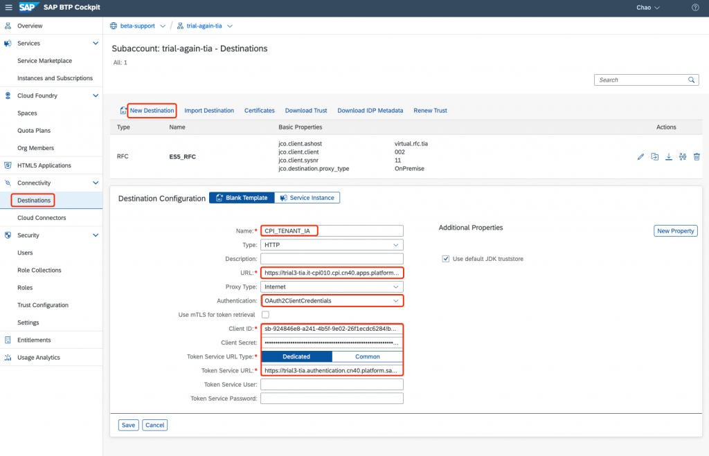
Choose Save.
3. Inject mapping artifacts
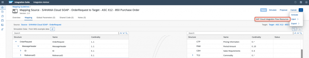
In the IA tenant, select the MAG from which you want to inject the mapping artifacts.
Choose the button in the right-upper corner, and then choose Inject -> SAP Cloud Integration Flow Resources.
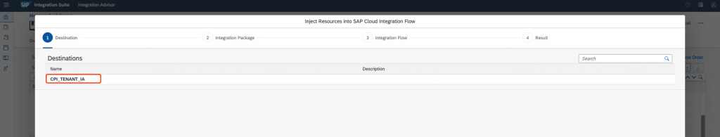
Choose an SAP Cloud Integration tenant from the Destinations list.
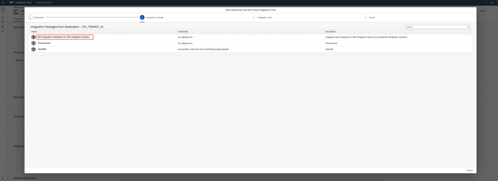
Choose the desired integration package from the list.
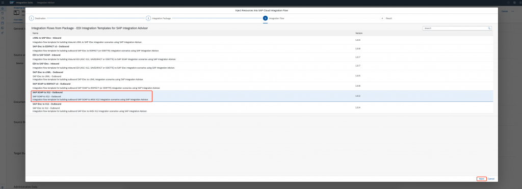
Select an integration flow from the list into which you want to inject the resources and choose Inject.
Now, you can see the injected artifacts from the integration flow view:
Step 3: Configure Integration Flow
1. SOAP Pre-Processing
In this step, the SOAP is preprocessed via an XSLT mapping.
Name: <SourceMIGName>__preproc.xsl
Resource: Runtime artefact from SAP IA. Located in the MIG source folder within the exported zip file.
Type: XSLT Mapping
Output Format: XML
2. SOAP to X12 Mapping
Mapping step where the SOAP message is transformed into the ASC X12 message via XSLT.
Name: <MAGName>.xsl
Resource: Runtime artefact from SAP IA. Located at the root folder of the exported zip file.
Type: XSLT Mapping
Output Format: XML
3. X12 Extended Validation (optional)
XML Validation step where the result of the XSLT mapping is validated against the ASC X12 extended validation XSD. Supports XSD 1.1 version.
This validation step is optional but recommended in case the generated payload needs to be validated against a xsd. E.g. for target message 810 4010, N1.98 qualified “BY” (Buying Party), N4.26 (country code) is restricted using a codelist only to value “DE”. If you don’t want to execute validation of the message, simply remove this flow step from your integration flow.
In this post, let’s remove the validator.
Name: <SourceMIGName>__RD.xsd
Resource: Runtime artefact from SAP IA. Located in the MIG target folder within the exported zip file.
Type: XSLT Mapping
Output Format: XML
4. X12 Post-processing
The qualifiers within the target ASCX12 message are removed via an XSLT mapping.
Name: <TargetMIGName>__postproc.xsl
Resource: Runtime artefact from SAP IA. Located in the MIG target folder within the exported zip file.
Type: XSLT Mapping
Output Format: XML
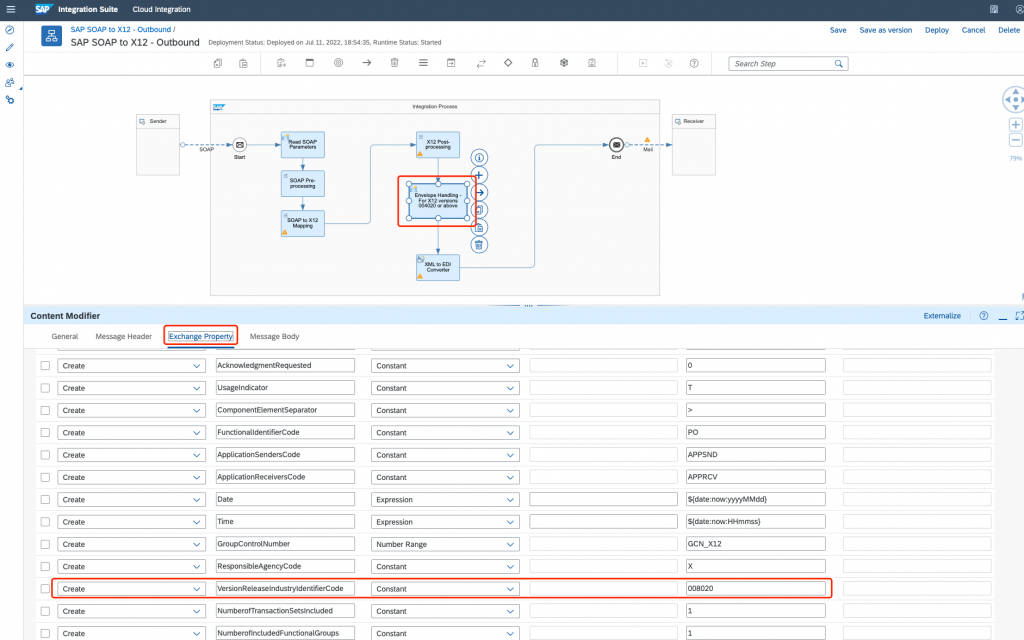
5. Envelope Handling
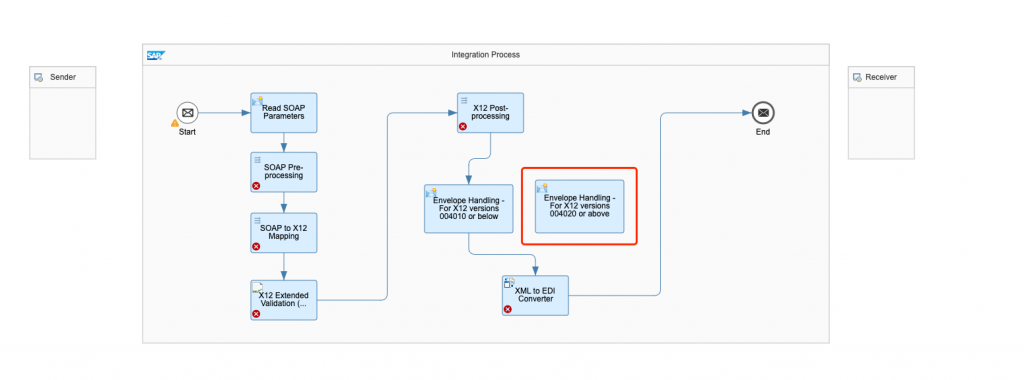
For X12 version ‘004020 or above’, change the Integration Flow: switch the connection lines from step “X12 Postprocessing” and towards step “XML to EDI Converter” such that the alternative step “Envelope handling – For X12 versions 004020 or above” is used.
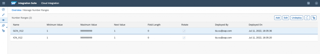
In case the requirement is to generate a new Interchange Control Number each time you are sending an ANSI X12 message, you can use Number Ranges.
A number range can be used to insert unique sequence numbers.
To configure Number Ranges, navigate to Monitor -> Manage Stores -> Number Ranges. For example:
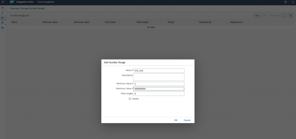
Rotate: To rotate next value once it reaches the maximum value.
Maximum Value: Each time an unique number is generated, the length will stay at 9 characters. This means 1 will become 000000001.
Update the X12 version accordingly:
6. XML To EDI Converter
Schema Name: ASC-X12<TransactionSet><MessageVersion>.xsd
Resource: Runtime artefact from SAP IA. Located in the MIG target folder within the exported zip file.
Source Encoding: e.g. UTF-8
EDI Schema Definition: Integration Flow
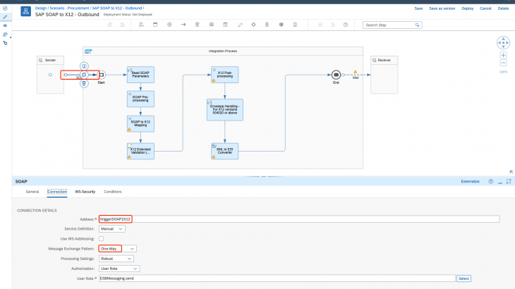
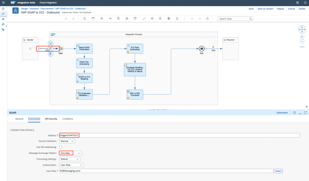
7. Sender
Add a SOAP connection, and configure the fields Address and Message Exchange Pattern:
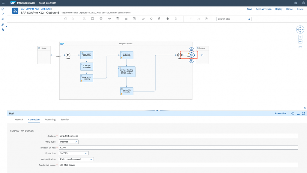
8. Receiver (optional)
You can set up a mail connection to notify you with the mapped payload. Otherwise, you can check the payload in the monitor of CI.
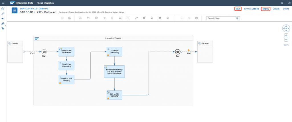
Step 3: Deploy Integration Flow
Save and deploy your integration flow:
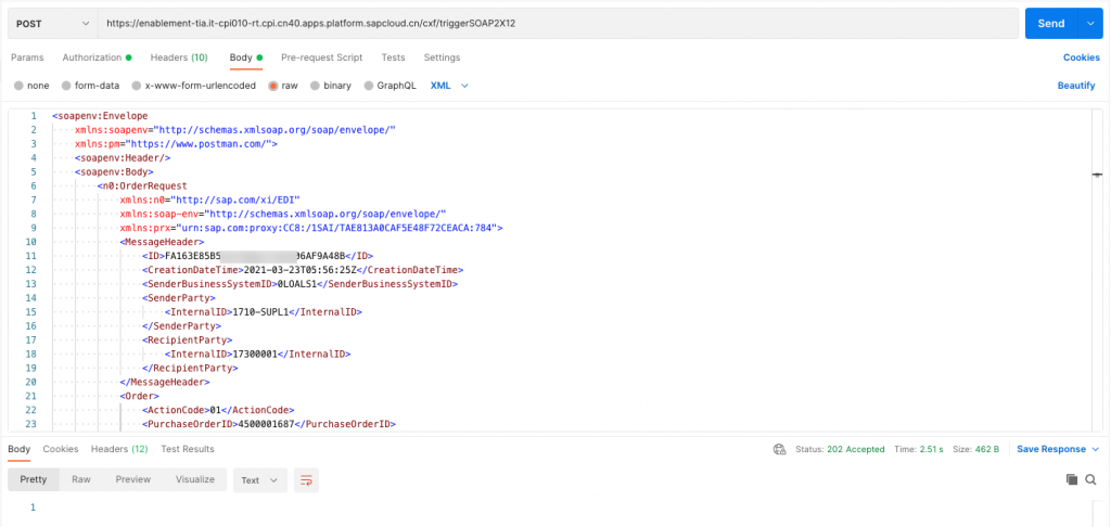
Step 4: Trigger Integration Flow
Once the integration flow has been successfully deployed. You can trigger the flow with S/4HANA Cloud or simply using Postman for quick test.
In this post, we use the Postman:
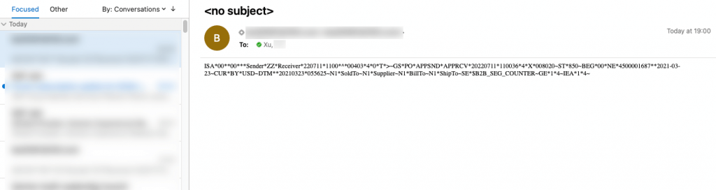
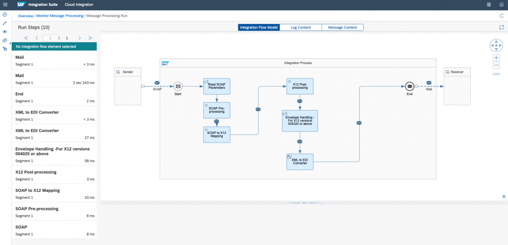
You can check the detailed payload in the Monitor Message Processing view:
If you set up the mail connection, you will receive an email attached with the mapped payload: